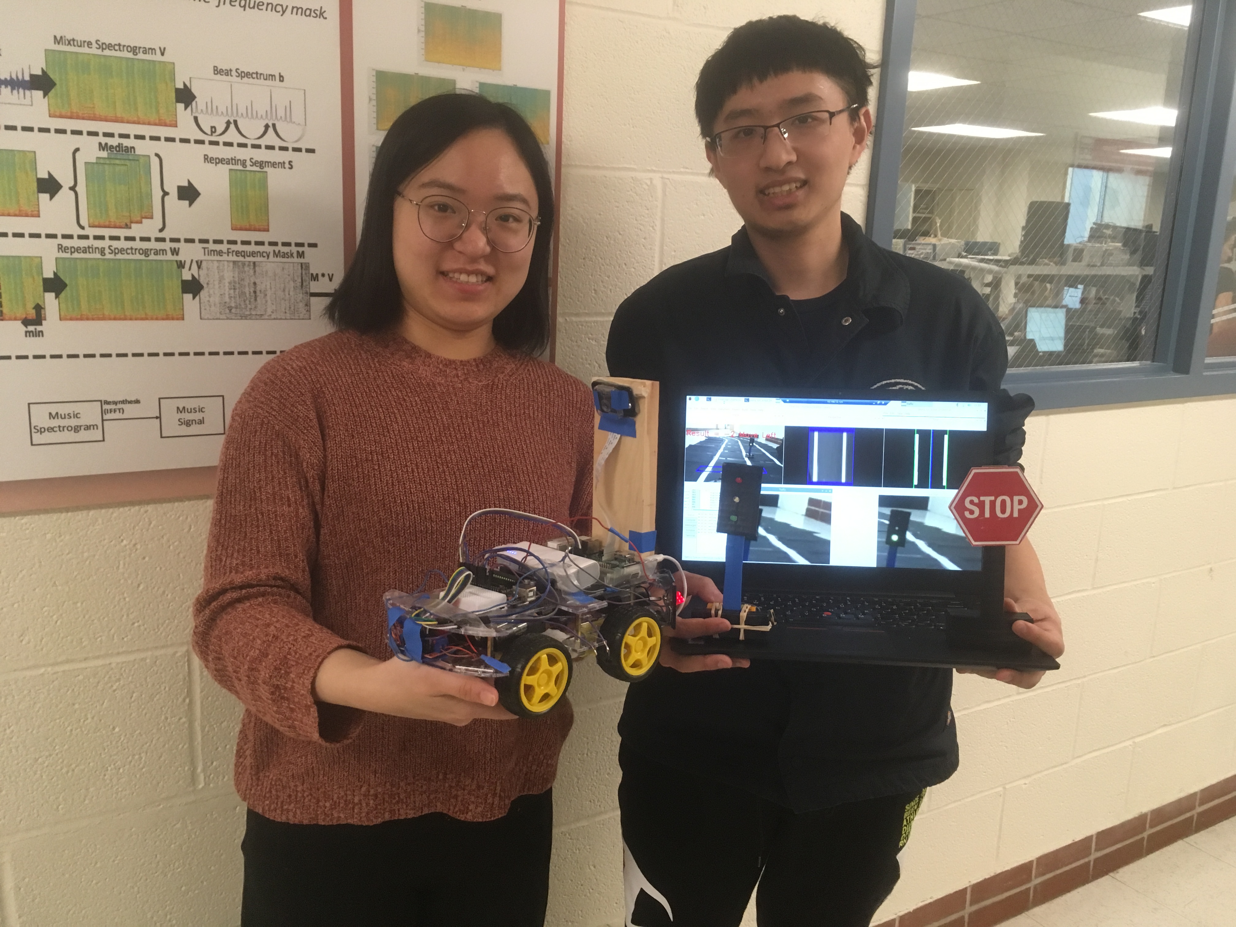
Yuhua Ma & Zhixin Lai
With the development of automation, robotics is revolutionizing how people do simple tasks in their daily life. At the same time, many high tech companies are now paying attention to self-driving technology, such as Waymo and Uber. In this project, we decided to design a self-driving car with a Raspberry Pi to operate in several driving scenarios, such as moving straight, turning, detecting traffic lights, detecting stop signs, and avoiding obstacles.
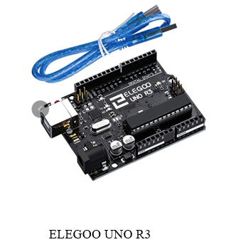
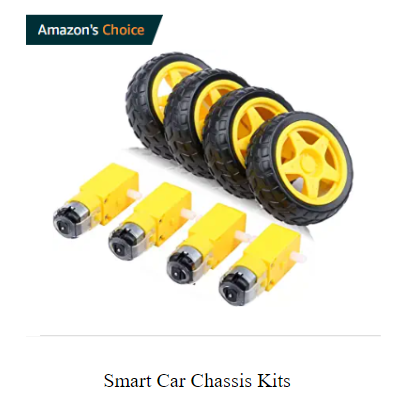
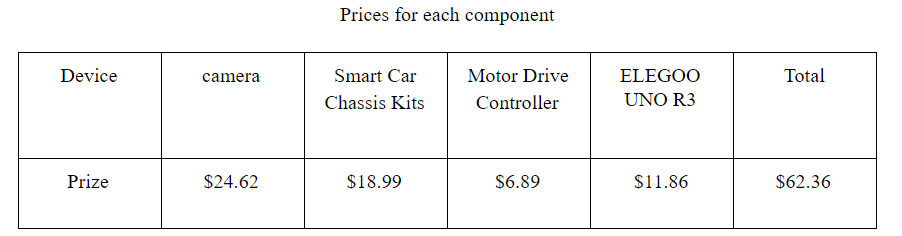
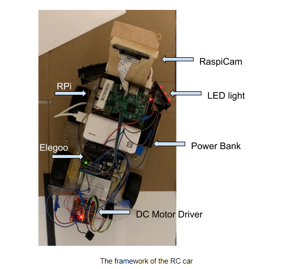
The hardware design of our self-driving car consists of a Smart Car Chassis Kit, a Raspberry Pi, a camera module, an ELEGOO, a Motor Drive Controller, a power bank, 6 LEDs, and 12 batteries. We have also created the lanes, stop sign, traffic light, and car obstacles for this project. As for the power supply, we used 8 batteries to supply 12V to power the motor driver, 4 batteries to supply 6V to power the Arduino, and a power bank to supply 5V to power the Raspberry Pi.
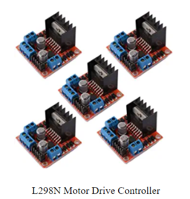
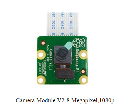
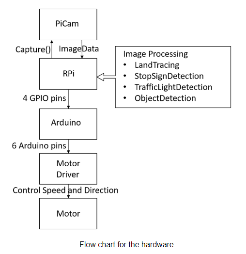
When the program executes, the Pi Camera captures images and sends data to the Raspberry Pi’s processor. Then, our processor analyzes the image data and sends corresponding signals to the Arduino through 4 GPIO pins. When our Arduino has received 4 bits from the Pi, it sends corresponding motor control signals to our L298N motor driver according to a state machine so that it can change four motors' rotation direction and rotation speed.
The following picture shows the remote desktop of the Raspberry Pi after we run the program.
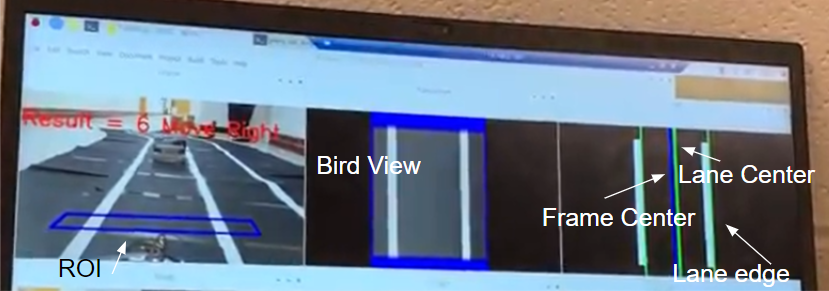
The blue box in the first frame shows the Range Of Interest (ROI) which will be used for further analysis. We put the car in the middle of the lane and define the ROI box’s four vertices by making sure two white lines are inside the box and parallel to the two edges.
The second frame shows the bird view of our ROI. This is realized by doing an image transformation. In addition, we change the storage of the image from a three-channel RGB image to a one-channel grey image, which is enough for further analysis.
The third frame shows a threshold segmentation result, detected lane edge, lane center, and frame center. For threshold segmentation, we tried using traditional image processing methods such as Canny Edge Detection, Dilation, and Histogram. Later, according to this issue, we find out that threshold segmentation is already enough for the tracing process. Therefore, we only kept threshold segmentation and histogram to reduce calculation overhead.
The variable Result is calculated by subtracting the calibrated _frameCenter_ from _laneCenter_. The car now judges direction by whether it is positive or negative, and decides its speed by the result’s absolute value.
For speed adjustment, we designed a gradient of different velocities for turning left and turning right. When the absolute value is small, we let the car make a slow turn. When we meet with large curvature on the trace, we let the car make a fast turn. We realize this function by taking into account both the Raspberry Pi’s code and the Arduino’s code. We designed 7 states: left1, left2, left3, forward, right1, right2, right3. These are used for tracing issues. The Pi calculates the variable Result in a timely manner and goes into different if statement branches according to the calculation result. The result is then sent by the Raspberry Pi's four GPIO pins to the Arduino. In the Arduino code, we use a pulse-width modulation (PWM) signal to control the motor's speed and change the wheel’s spinning direction by adjusting the High/Low pin, allowing the current direction in the motor to change. Then, with the help of a state machine, our Arduino sends the corresponding instruction to the motor driver by using three pins for the left motor pair and three pins for the right motor pair.
In order to realize the function of detection and the corresponding logic, we trained the detection model. First, we collected training data and then used the data to train the model. Second, we load the model in the main function and predict the distance between the car and the object. Third, according to the result of the ML model, we wrote the C/C++ code for the Arduino to control the movement of the car. The flow chart is shown as follows.
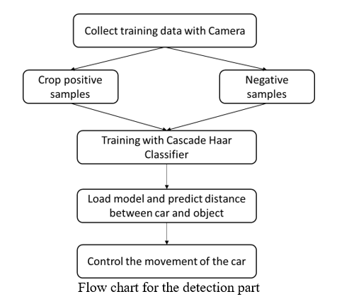
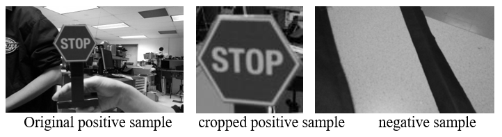
Data collection is a primitive for the training model. The model is not complex, and the detection task is simple. Because of this, we decided to collect data with 60 positive samples and 300 negative samples for the stop sign, traffic light, and car obstacles.
First, we took the photos for the traffic light model and transferred the RGB images into gray images. Second, we cropped the positive samples from the positive images. Third, we regulated the size of the image.
The Raspberry Pi has 1G RAM and it is hard to run a big model in the Pi, like ResNet or VGG. Therefore, we selected a small detection model known as a Cascade Haar Classifier.
A Haar Cascade is basically a classifier that is used to detect the object for which it has been trained for based on the training data. The idea of Haar Cascade is to extract features from images using a type of ‘filter’, similar to the concept of the convolution kernel. These filters are called Haar features, which are shown below:
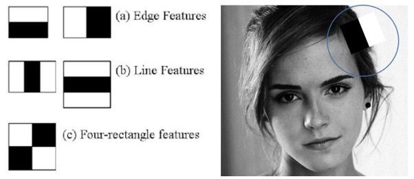
The idea is to pass these filters on the image and inspect one portion or window at a time. Then, for each window, all the pixel intensities of the respective white and black portions are summed. Finally, the value obtained by subtracting those two summations is the value of the feature extracted.
Finally, we utilized the OpenCV4 to load the Cascade Haar Classifier trained in the previous step.
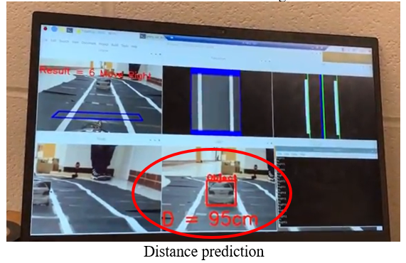
In order to control the car with higher accuracy, we thought about a simple method to predict the distance between the car and the traffic light model. The projection is linear, and the object in the 2D image is linear with the real object. If the real object is larger in the same place, the car in the 2D image looks larger. If the same object is placed closer to the camera, the car in the 2D image appears larger. Therefore, we selected several distances and corresponding sizes for the 2D boxes. We utilized the points to fit a linear curve with the function distance = wx + b, where w is the weight, x is the box width size, and b is the bias. After getting the linear function, we utilized it to predict the distance between the car and traffic infrastructure with the 2D boxes in the image.
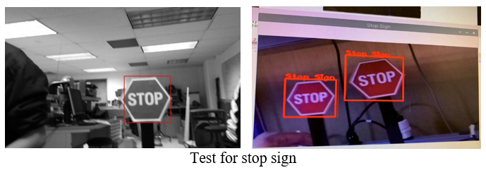
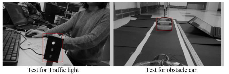
Once the car detects the stop sign in front of the car within a certain distance, the Raspberry Pi will send the signal to the Arduino. The Arduino would control the car to stop for 4 seconds and then move forward. Once the car detects the traffic light in front of the car within a certain distance, the Raspberry Pi will send the signal to the Arduino. The Arduino would control the car to stop until the light turns green. Once the car detects the car obstacle in front of the car within a certain distance, the Pi will send the signal to the Arduino. The Arduino then controls the car to change to another lane and follow the lane automatically.
As we can see from the video, our car changes its turning direction and speed according to the Result variable calculated by the Raspberry Pi's processor. The left LED light blinks when the car is making a left turn and the right LED light blinks when the car is turning right. When the car moves forward, the LED lights all turn off.
As we can see from the video, our car recognizes the stop sign when the sign is within the detection distance we set. It stops for 4 seconds and then continues its lane tracking process.
As we can see from the video, our car recognizes the red traffic light and stops. It remains in the stop state until the light turns green. Then our car continues its lane tracking process.
As we can see from the video, our car recognizes the car obstacle and starts a lane changing process. Since calculation for object detection is time-consuming, especially for the model of the car obstacle, our car sometimes cannot receive instructions in a timely manner to adjust its running speed and direction when all the object detection methods are included in the image processing period. Some tips to improve calculation speed and solve this problem are mentioned below.
When we do test cases for our self-driving car, several tips can be used to adjust its related parameters and improve performance.
Since the battery voltage may decrease after being used for a while, the motor’s speed tends to vary even with the same control signal. We can choose to change/decrease the value of _if_ branch, or we can change the Arduino code and improve the PWM signal for the motors so that our car can adjust its track more quickly.
After running the classifier model, the run time for each loop becomes longer, which had a bad effect on the tracking accuracy. In order to reduce the bad influence, we tried to crop the original image for detection input. The responding time of tracking becomes less after reducing the size of the input image for detection.
Another way to reduce the bad influence of the detection model is to define a concurrent relationship between how often the car is tracking the lane compared to how long it's detecting objects. We defined the ratio of each operation as 10 tracking cycles to one detection cycle respectively. The reaction time of the car reduces after the regulation period.
ym474@cornell.edu
zl768@cornell.edu
                #include <opencv2/opencv.hpp>
                #include <raspicam_cv.h>
                #include <iostream>
                #include <chrono>
                #include <ctime>
                #include <wiringPi.h>

                using namespace std;
                using namespace cv;
                using namespace raspicam;


                int pin1 = 21;
                int pin2 = 22;
                int pin3 = 23;
                int pin4 = 24;
                // Image Processing variables
                Mat frame, Matrix, framePers, frameGray, frameThresh, frameEdge, frameFinal, frameFinalDuplicate, frameFinalDuplicate1, test;
                Mat ROILane, ROILaneEnd;
                int LeftLanePos, RightLanePos, frameCenter, laneCenter, Result, laneEnd;
                stringstream ss;


                RaspiCam_Cv Camera;

                vector<int> histrogramLane;
                vector<int> histrogramLaneEnd;
                vector<int> histrogramReverse;

                Point2f Source[] = {Point2f(65,175),Point2f(320,175),Point2f(45,195), Point2f(334,195)};//
                Point2f Destination[] = {Point2f(100,0),Point2f(280,0),Point2f(100,240), Point2f(280,240)};


                // Machine Learning variables
                CascadeClassifier Stop_Cascade, Object_Cascade, Traffic_Cascade;
                Mat frame_Stop, RoI_Stop, gray_Stop, frame_Object, RoI_Object, gray_Object, frame_Traffic, RoI_Traffic, gray_Traffic;
                vector<Rect> Stop, Object, Traffic;
                int dist_Stop, dist_Object, dist_Traffic;

                clock_t TIME_stop = 6 * 1000 * 1000, stop_time = -TIME_stop;
                clock_t TIME_object = 3 * 1000 * 1000, object_time = -TIME_object;
                clock_t TIME_traffic = 6 * 1000 * 1000, traffic_time = -TIME_traffic;
                clock_t TIME_laneend = 6 * 1000 * 1000, laneend_time = -TIME_laneend;

                // camera setup
                void Setup ( int argc,char **argv, RaspiCam_Cv &Camera )
                  {
                    Camera.set ( CAP_PROP_FRAME_WIDTH,  ( "-w",argc,argv,400 ) );
                    Camera.set ( CAP_PROP_FRAME_HEIGHT,  ( "-h",argc,argv,240 ) );
                    Camera.set ( CAP_PROP_BRIGHTNESS, ( "-br",argc,argv,50 ) );
                    Camera.set ( CAP_PROP_CONTRAST ,( "-co",argc,argv,50 ) );
                    Camera.set ( CAP_PROP_SATURATION,  ( "-sa",argc,argv,50 ) );
                    Camera.set ( CAP_PROP_GAIN,  ( "-g",argc,argv ,50 ) );
                    Camera.set ( CAP_PROP_FPS,  ( "-fps",argc,argv,0));

                }

                // capture image
                void Capture()
                {
                    Camera.grab();
                    Camera.retrieve( frame);
                   // cvtColor(frame, frame_Stop,COLOR_BGR2RGB);
                   // cvtColor(frame_Stop, frame_Stop,COLOR_RGB2BGR);
                   frame_Stop = frame.clone();
                   frame_Object = frame.clone();
                   frame_Traffic = frame.clone();
                }

                // tranform to bird view perspective
                void Perspective()
                {
                  line(frame,Source[0], Source[1], Scalar(255,0,0), 2);
                  line(frame,Source[1], Source[3], Scalar(255,0,0), 2);
                  line(frame,Source[3], Source[2], Scalar(255,0,0), 2);
                  line(frame,Source[2], Source[0], Scalar(255,0,0), 2);

                  Matrix = getPerspectiveTransform(Source, Destination);
                  warpPerspective(frame, framePers, Matrix, Size(400,240));

                  for(int i = 0; i < framePers.rows; i++)
                  {
                      for(int j = 0; j < framePers.cols; j++)
                      {
                    // change left and right part's pixel value from black to white
                    // so that black track edge can be distinguished from left and right part in the threshold() function
                    if(j > 280 || j < 100)//framePers.ptr(i)[j]==cv::Vec3b(0,0,0))
                    {
                        *(framePers.data + framePers.step[0] * i + framePers.step[1] * j + framePers.elemSize1() * 0) = 0;
                        *(framePers.data + framePers.step[0] * i + framePers.step[1] * j + framePers.elemSize1() * 1) = 0;
                        *(framePers.data + framePers.step[0] * i + framePers.step[1] * j + framePers.elemSize1() * 2) = 0;
                    }
                      }
                  }
                }

                void Threshold()
                {
                  cvtColor(framePers, frameGray, COLOR_RGB2GRAY);
                  inRange(frameGray, 160, 255, frameThresh);//[][][]
                  /*
                  // get rid of white spots on two lines caused by Perspective()
                  //   find white spots
                  Canny(frameGray,frameEdge, 600, 800, 3, false);//[][][]
                  test = frameEdge;
                  //   amplify white spots using dilate
                  Mat element = getStructuringElement(MORPH_RECT, Size(15, 15));//[][][]
                  dilate(frameEdge, frameEdge, element);

                  //   get rid of white spots by adding two images
                  frameGray = frameGray + frameEdge;
                  */
                  //Canny(frameGray,frameEdge, 300, 700, 3, false);//[][][]
                  //add(frameThresh, frameEdge, frameFinal);
                  cvtColor(frameThresh, frameFinal, COLOR_GRAY2RGB);
                  cvtColor(frameFinal, frameFinalDuplicate, COLOR_RGB2BGR);   //used in histrogram function only
                  cvtColor(frameFinal, frameFinalDuplicate1, COLOR_RGB2BGR);   //used in histrogram function only
                }

                void Histrogram()
                {
                    histrogramLane.resize(400);
                    histrogramLane.clear();

                    for(int i=0; i<400; i++)
                    {
                  ROILane = frameFinalDuplicate(Rect(i,140,1,100));
                  divide(255, ROILane, ROILane);
                  histrogramLane.push_back((int)(sum(ROILane)[0]));
                    }

                    histrogramLaneEnd.resize(400);
                    histrogramLaneEnd.clear();
                    for (int i = 0; i < 400; i++)
                    {
                  ROILaneEnd = frameFinalDuplicate1(Rect(i, 0, 1, 240));
                  divide(255, ROILaneEnd, ROILaneEnd);
                  histrogramLaneEnd.push_back((int)(sum(ROILaneEnd)[0]));
                    }
                   laneEnd = sum(histrogramLaneEnd)[0];
                }

                void LaneFinder()
                {
                    vector<int>:: iterator LeftPtr;
                    LeftPtr = max_element(histrogramLane.begin(), histrogramLane.begin()+190);
                    LeftLanePos = distance(histrogramLane.begin(), LeftPtr);

                    vector<int>:: iterator RightPtr;

                    histrogramReverse.resize(400);

                    histrogramReverse.assign(histrogramLane.begin(), histrogramLane.end());
                    reverse(histrogramReverse.begin(), histrogramReverse.end());


                    RightPtr = max_element(histrogramReverse.begin(), histrogramReverse.begin()+190);
                    RightLanePos = 400 - distance(histrogramReverse.begin(), RightPtr);

                    line(frameFinal, Point2f(LeftLanePos, 0), Point2f(LeftLanePos, 240), Scalar(0, 255,0), 2);
                    line(frameFinal, Point2f(RightLanePos, 0), Point2f(RightLanePos, 240), Scalar(0,255,0), 2);
                }

                void LaneCenter()
                {
                    laneCenter = (RightLanePos-LeftLanePos)/2 +LeftLanePos;
                    frameCenter = 188;

                    line(frameFinal, Point2f(laneCenter,0), Point2f(laneCenter,240), Scalar(0,255,0), 3);
                    line(frameFinal, Point2f(frameCenter,0), Point2f(frameCenter,240), Scalar(255,0,0), 3);

                    Result = laneCenter-frameCenter;
                }

                void Stop_detection()
                {
                    if(!Stop_Cascade.load("//home//pi//Desktop//Stop_cascade.xml"))
                    {
                  printf("Unable to open stop cascade file");
                    }

                    RoI_Stop = frame_Stop(Rect(250,40,100,70));//200,0,200,140
                    cvtColor(RoI_Stop, gray_Stop, COLOR_RGB2GRAY);
                    equalizeHist(gray_Stop, gray_Stop);
                    Stop_Cascade.detectMultiScale(gray_Stop, Stop);
                    dist_Stop = 0;

                    for(int i=0; i<Stop.size(); i++)
                    {
                  Point P1(Stop[i].x, Stop[i].y);
                  Point P2(Stop[i].x + Stop[i].width, Stop[i].y + Stop[i].height);

                  rectangle(RoI_Stop, P1, P2, Scalar(0, 0, 255), 2);
                  putText(RoI_Stop, "Stop Sign", P1, FONT_HERSHEY_PLAIN, 1,  Scalar(0, 0, 255, 255), 2);
                  std::cout<P2.x-P1.x<std::endl;
                  dist_Stop = (-2)*(P2.x-P1.x) + 166;//[][][]
                        ss.str(" ");
                        ss.clear();
                        ss<<"D = "<<dist_Stop<<" (cm)";
                        putText(RoI_Stop, ss.str(), Point2f(1,130), 0, 0.5, Scalar(0,0,255), 2);

                    }

                }

                void Object_detection()
                {
                    if(!Object_Cascade.load("//home//pi//Desktop//Object_cascade.xml"))
                    {
                  printf("Unable to open Object cascade file");
                    }

                    RoI_Object = frame_Object(Rect(120,80,160,120));//(100,0,200,140)
                    cvtColor(RoI_Object, gray_Object, COLOR_RGB2GRAY);
                    equalizeHist(gray_Object, gray_Object);
                    Object_Cascade.detectMultiScale(gray_Object, Object);

                    dist_Object = 0;
                    for(int i=0; i<Object.size(); i++)
                    {
                  Point P1(Object[i].x, Object[i].y);
                  Point P2(Object[i].x + Object[i].width, Object[i].y + Object[i].height);

                  rectangle(RoI_Object, P1, P2, Scalar(0, 0, 255), 2);
                  putText(RoI_Object, "Object", P1, FONT_HERSHEY_PLAIN, 1,  Scalar(0, 0, 255, 255), 2);
                  std::cout<<P2.x-P1.x<<std::endl;
                  dist_Object = (-1.36)*(P2.x-P1.x) + 165;

                        ss.str(" ");
                        ss.clear();
                        ss<<"D = "<<dist_Object<<"cm";
                        putText(RoI_Object, ss.str(), Point2f(1,130), 0,1, Scalar(0,0,255), 2);

                    }

                }

                void Traffic_detection()
                {
                    if(!Traffic_Cascade.load("//home//pi//Desktop//Traffic_cascade.xml"))
                    {
                  printf("Unable to open traffic cascade file");
                    }

                    RoI_Traffic = frame_Traffic(Rect(250,40,100,70));//(200,0,200,140)
                    cvtColor(RoI_Traffic, gray_Traffic, COLOR_RGB2GRAY);
                    equalizeHist(gray_Traffic, gray_Traffic);
                    Traffic_Cascade.detectMultiScale(gray_Traffic, Traffic);\

                    dist_Traffic = 0;
                    for(int i=0; i<Traffic.size(); i++)
                    {
                  Point P1(Traffic[i].x, Traffic[i].y);
                  Point P2(Traffic[i].x + Traffic[i].width, Traffic[i].y + Traffic[i].height);

                  rectangle(RoI_Traffic, P1, P2, Scalar(0, 0, 255), 2);
                  putText(RoI_Traffic, "Traffic Light", P1, FONT_HERSHEY_PLAIN, 1,  Scalar(0, 0, 255, 255), 2);
                  std::cout<<P2.x-P1.x<<std::endl;
                  dist_Traffic = (-3)*(P2.x-P1.x) + 153;

                        ss.str(" ");
                        ss.clear();
                        ss<<"D = "<<dist_Traffic<<"cm";
                        putText(RoI_Traffic, ss.str(), Point2f(1,130), 0,1, Scalar(0,0,255), 2);

                    }

                }
Follow more code on Github:
self-driving-car-with-Rasiberry-Pi